-
Advanced NDT
- ACFM
- 3D Laser Scanning
- Infared Thermography
- Pulsed Eddy Current
- Eddy Current Surface Array
- Videoscopic Inspection
- UAV / Drone Inspection
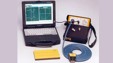
Alternating Current Field Measurement (ACFM) Testing
ACFM® is an electromagnetic inspection technique that introduces an alternating current into the surface of the component to detect surface-breaking cracks. The presence of a crack disturbs the electromagnetic field and the return signal is instantaneously converted by advanced mathematical techniques, so that the operator is alerted to the presence of a defect. Immediate defect sizing and recording is a major benefit compared to alternative NDT methods.

APPLICATIONS
- Crack detection in any orientation
- Can be applied on ferrous and non-ferrous materials.
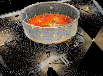
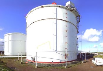
3D Laser Scanning
Laser scanning using LIDAR (Light Detection and Ranging), is a new inspection technology that provide faster, safer and better coverage of any structure. The 3D laser scanner is used to capture millions of individual points on buildings, storage tank’s shell, bottom and roof and the data can be used for fitness-for-service assessments (FFS).
API 653 standards require measured data on the verticality of tank shells, the roundness of tank shells, flatness of the tank bottom and any subsidence.
Laser scanning also captures information on appurtenances such as nozzles, access points, stairs and ladders as well as nearby structures and terrain. Built-in cameras capture digital images that provide additional documentation of tank conditions.
Software is used to take data from an inspection and automatically merge multiple point clouds into a single cohesive dataset. With the software enabling basic clean-up and organization, and the resulting point cloud provides a comprehensive and precise picture of the inspection, enables users to create high-density 3D digital representations of storage tanks, analyse the data following API 653 Standard guidelines and automatically detect out-of-tolerance areas
APPLICATIONS
- Storage Tank measurement and calibration
- Storage tank settlement and deformation survey and Fitness for service assessments(FFS)
- Construction structures, buildings, jetty, oil rig platforms, FPSO’s and ship platforms.
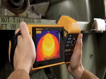
Infared Thermography
IR thermography is used to measure temperature variances of a component as heat flows through, from, or to that component. Images of the detected temperature distribution are called thermograms, is used to confirm machinery is running normally and to detect abnormal heat patterns within a machine, indicating inefficiency and defects and they make it possible to see heat-producing objects invisible to the naked eye.
The primary goal of infrared thermography IR thermography is utilized in many industries and applications. In the oil and gas and chemical processing industries, for example, thermography can be used to detect piping insulation issues, fluid levels, or identify trouble spots where rotating equipment is experiencing too much friction. Furthermore, IR testing is commonly used to locate hot spots and anomalies such as voids and inclusions. The benefits of IR testing include extended equipment life, decreased unscheduled shutdowns, reduced risk of equipment failure, and increased performance.
APPLICATIONS
- Predictive Maintenance and Condition Monitoring
- Piping and Pressure Vessel Insulation issues
- locate hot spots and anomalies such as voids and inclusions
- heating, ventilation and air conditioning (HVAC) equipment’s
- Energy audits
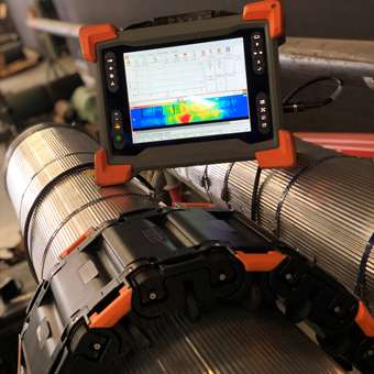
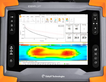
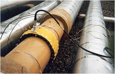
Pulsed Eddy Current
PEC can be applied to in-service assets, and can detect damages through thick insulation such as aluminium, stainless steel and galvanized steel weather jackets. It is an effective tool for corrosion-under-insulation (CUI) and flow-accelerated corrosion (FAC) assessments.
PEC can be done without need for contact with the surface of the material. Because of this, it can be useful in situations where an object’s surface is rough or inaccessible. This method also doesn’t require surface preparation or removing any insulation. It can be a quick and cost-effective solution for corrosion detection.
APPLICATIONS
- Corrosion under Insulation(CUI)
- Insulated pipes and vessels
- Corrosion under fire proofing
- Underwater and splash zone structure inspection
- Storage tanks, marine vessels
Eddy Current Surface Array
ECA probes are designed to be flexible and is capable of finding flaws with better detection capabilities techniques. With ECA larger area can be scanned at one time while maintaining a high resolution and wider coverage. The method is less operator dependent with easier data analysis because of simpler scan patterns and C-scan imaging and permanent data recording of inspection data.
Furthermore, materials and welds can be using ECA without removing paint or protective non-conductive coatings (up to 3mm lift-off), unlike more conventional techniques. Complex shapes can be inspected using this method because the probes can be customized to the profile of the part being inspected.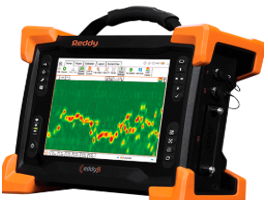
APPLICATIONS
- Detect and size the length and depth of longitudinal surface-breaking cracks in carbon steel welds
- It can also be used to detect transverse surface-breaking cracks.
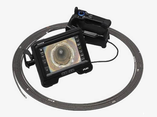
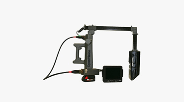
Videoscopic Inspection
The portable industrial videoscope camera is a great tool for inspection and maintenance, of difficult to reach areas of pipelines, pressure vessels and equipment’s. These videoscope’s offer users a new perspective of visual inspection through high quality detailed images of the test item with its flexible cables, lightweight enclosure, and highly illuminated camera. Using these cameras, we can locate problems very easily and quickly, allowing for preventative measures to be taken without the need to dismantle the machinery, or system.
The videoscope camera equipped with articulation tip enables to control focus and view target area with precise movement. Videoscope equipped with scalar measurement tools allows to size defects and anomalies.
APPLICATIONS
- Pipelines, pressure vessels.
- Pharmaceutical industry and food grade equipment’s.
- Heat exchanger tubes.
- Turbines and machinery
- Manufacturing industry
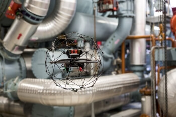
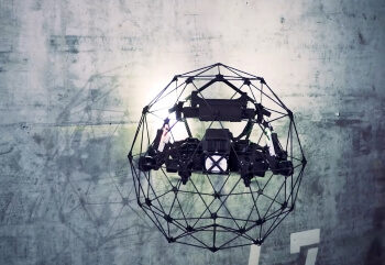
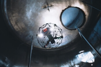
Unmanned Aerial Vehicles (UAVs) / Drone Inspection
Unmanned Aerial Vehicles (UAV), or Drones are simply any aircraft that does not have a human pilot.
UAV are primarily used for visual inspection to keep your workforce out of harm’s way while performing flawless inspections using cutting edge drone data capture capabilities. High resolution(HD) cameras with the option of thermography(IR) images, allow them to get a close up, accurate view of a structure, even from a great distance. GPS enabled image stabilization,
They can be used to inspect nearly any structure, both indoors and outdoors, but they are most useful in the inspection of structures that are difficult to reach by traditional means. Data visualization is taken to the next level of 2D data measurements such as measuring length and dimensions of the inspected items.
Compared to traditional inspection, the use of UAV is cheaper, faster, and safer, without requiring shutdown, the construction of scaffolding, or sending inspectors into dangerous situations.
UAV have a range of uses in variety of fields including recreational, commercial, or military purposes.
APPLICATIONS
- Quick overview and evaluation of hard to reach areas
- Tall structures, such as flare stacks, cooling towers, elevated pipe trays, chimney and smoke stack.
- Storage tanks, Aerial survey.
- Confined spaces in which space is limited for traditional inspections.
- Structures that are over water such as bridges, jetty or the undersides of oil rig platforms, FPSO’s and ship platforms.
-
Advanced Radiography
Open Vision Radiography
Corrosion under insulation (CUI) is the corrosion of piping and vessels that occurs beneath insulation as a result of water penetration. The water can come from rain water, leakage, deluge system water, wash water, or sweating from temperature cycling or low temperature operation such as refrigeration units.
Unfortunately, because the corrosion is hidden under the insulation, CUI tends to remain undetected until the insulation is removed for inspection or when leaks occur. CUI is a common problem across many industries, including refining, petrochemical, power, industrial, onshore and offshore industries.
APPLICATIONS
- Detecting damage such as moderate to heavy corrosion under insulation (CUI), moderate to heavy pitting, and pipes distorted from mechanical damage.
- It can also find things such as welds or transverse joints under insulation.
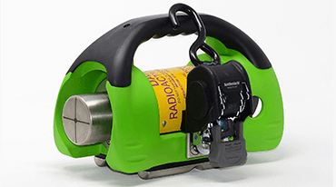
SCAR Radiography
Small Controlled Area Radiography (SCAR) SCAR-a directional gamma radiography system for use in areas congested with workers, confined spaces, or where radiation output must be kept to an absolute minimum so not to disrupt normal operations. SCAR utilizes a compact exposure device with built-in collimation to enhance the ability for radiographic inspection to be performed more safely and with equal, if not higher, levels of productivity compared to traditional gamma exposure devices. SCAR allows for smaller restrictive barricades, eliminates flash dose to radiographic personnel, and may increase the overall productivity of radiography crews when utilized in congested areas where increased manpower is present, such as plant shutdowns.
APPLICATIONS
- Radiation Barricade distance only 5M Radius
- No need to Stop other activities
- Can be used with Se75 Source which gives high quality Radiographs
Computed Radiography
Computed Radiography (CR) is the production of a digital image by using a Phosphor Imaging Plate (IP) in place of conventional film.The Image (storage) Plate (IP) is exposed with X-ray or Gamma radiation, which causes the IP phosphor layer in the plate to store the X-ray image. During the reading process of the plate in the scanner, a focused laser beam triggers the release of the stored image data in the form of visible light. The emitted light is detected, captured, and converted into electrical signals which are digitized and finally displayed as a digital image on the PC monitor. The internal in-line eraser purges the residual data from the IP, which is then ready for the next exposure.
APPLICATIONS
- Utilized for rapid detection and sizing of cracking and weld flaws
- Typically used on heavy wall reactors or vessels in lieu of industrial radiography
- Can be combined with Phased Array to provide higher POD and more accurate classification of defects
- The detection of cracking
Digital Radiography
An X-ray beam is focused at the imaging detector. In medical applications the anatomy of the patient that needs to be examined is positioned in front of the detector. As the beam passes through the anatomy and hits the detector it is filtered by a scintillator.
The scintillator comes in different substrate materials and in this application it is most often Cesium Iodide (CsI) or Gadolinium Oxysulphide or Gaddox (GdOS). The scintillator emits light from exposure to the X-ray beam and is deflected by a mirror on to a lens which focuses the light onto the 9 or 16 Megapixels of the CCD dependant of the platform of IDC technology.


APPLICATIONS
- Corrosion, Pitting in Insulated Pipelines
- Process Pipelines Corrosion Findings
- No need to remove insulations
- Weld Inspection for Quick Review
- Profile Radiography for Corrosion Findings
-
Advanced Ultrasonic Testing
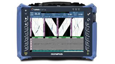
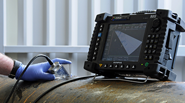
Phased Array Ultrasonic Testing
(PAUT) – Corrosion Mapping
An array transducer is simply one that contains a number of separate elements in a single housing, and phasing refers to how those elements are sequentially pulsed. A phased array system is normally based around a specialized ultrasonic transducer that contains many individual elements (typically from 16 to 256) that can be pulsed separately in a programmed pattern. These transducers may be used with various types of wedges, in a contact mode, or in immersion testing.
APPLICATIONS
- High Resolution Imaging (Both Lateral and Vertical Axes)
- Completely focused in entire volume
- Improved Signal to Noise Ratio (SNR)
- Oriented defects (e.g. cracks) are imaged better
- Easy to size flaws
Phased Array Ultrasonic Testing
PAUT – Total Focusing Method ( TFM )
Designed to address the requirements of elevated temperature corrosion and weld inspections, these solution packages are targeted at the reduction or elimination of shutdown times in production environments. This series is designed to operate up to 200°C. The TempMaster Gold solution package has been designed to include all the required equipment to ensure safe and reliable operation within this temperature range. The Gold Series high temperature material has a safety margin to accommodate some temperature fluctuation.
APPLICATIONS
Predictive Maintenance and Condition Monitoring
- Long lengths of pipes
- Corrosion under Insulation Splash zone inspection
- Un-piggable pipelines
- Jetty pipe work
- Buried pipelines & Road crossings
Phased Array Ultrasonic Testing
(PAUT) – High Temperature
An array transducer is simply one that contains a number of separate elements in a single housing, and phasing refers to how those elements are sequentially pulsed. A phased array system is normally based around a specialized ultrasonic transducer that contains many individual elements (typically from 16 to 256) that can be pulsed separately in a programmed pattern. These transducers may be used with various types of wedges, in a contact mode, or in immersion testing.
APPLICATIONS
- High Resolution Imaging (Both Lateral and Vertical Axes)
- Completely focused in entire volume
- Improved Signal to Noise Ratio (SNR)
- Oriented defects (e.g. cracks) are imaged better
- Easy to size flaws
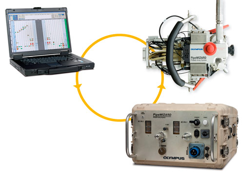
Automated Ultrasonic Testing (AUT)
In AUT of pipeline girth welds a phased array & TOFD probes are mounted on a band strapped around the pipe adjacent to the weld and is driven around the pipe’s circumference. As the probe(s) travel around the pipe, ultrasonic data are collected from the weld and the software enables flaw sizes and positions to be displayed. AUT is replacing radiography for pipeline girth weld inspections worldwide for both onshore and Offshore.Very fast scanning speeds , to keep pace with construction, it is necessary to complete a weld inspection less than 2 mints 0f 48” dia.
APPLICATIONS
- Inspect pressure vessels, piping, storage tanks, spheres, and other equipment while in service for potential damage
- Offers a full volumetric inspection providing details on shell material degradation such as erosion, corrosion, hydrogen blisters, hydrogen induced cracking (HIC), and related interlinking cracking
Time of Flight Diffraction (TOFD)
Although time-of-flight diffraction (TOFD) can be used for a variety of applications, its primary use is rapid weld testing of circumferential and axial weld seams, also known as perpendicular TOFD scanning. Since the introduction of TOFD in the 1970s, the use of this reputed reliable non destructive testing technique has steadily increased. Manual execution is possible with TOFD, however, it is most commonly performed in combination with a recording device, that is, an encoder or industrial scanner. To achieve code compliance in North America, TOFD is often coupled with pulse-echo or phased array techniques in order to cover the root and cap regions of the weld.
APPLICATIONS
- Utilized for rapid detection and sizing of cracking and weld flaws
- Typically used on heavy wall reactors or vessels in lieu of industrial radiography
- Can be combined with Phased Array to provide higher POD and more accurate classification of defects
- The detection of cracking
LONG RANGE UT (GUIDED WAVE ULTRASONIC TESTING)
The Guided Wave technology uses a low frequency guided ultrasound waves traveling along the pipe, providing 100% coverage of the pipe length. In normal application, tens of meters of piping may be inspected from a single location. Effected areas are precisely located in terms of distance from the transducer ring and highlighted for further local examination by visual or other conventional NDT methods. This non-destructive screening technique can be used without extensive scaffolding and minimizes the requirement of removing insulation along the piping.

APPLICATIONS
Predictive Maintenance and Condition Monitoring
-
- Long lengths of pipes
- Corrosion under Insulation Splash zone inspection
- Un-piggable pipelines
- Jetty pipe work
- Buried pipelines & Road crossings